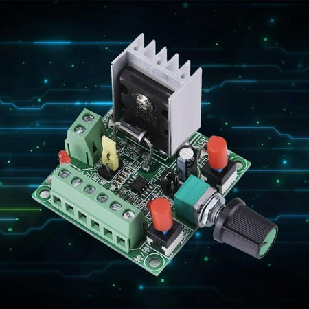
Stepper Motor Driver Controller PWM Pulse Signal Generator Speed Regulator

Fancy
sku: 2791399468
ACCORDING TO OUR RECORDS THIS PRODUCT IS NOT AVAILABLE NOW
$17.49
Shipping from: United States
Description
Features: brand new high quality Made of high quality material durable This module is provided as a stepper drive signal. To control a stepper motor a driver is also required. The controller has high medium and low frequency signals which can be used to select jumpers. The measurement frequency can be two ports of PUL and common cathode terminal (GND). PUL+ and PUL- pulse positive and negative; EN+ and EN——used to enable positive and negative terminals; DIR + and DIR - are positive and negative directions. These six wires are connected to drive the corresponding pulse direction so six ports are possible. Power supply: 15-160VDC or 5-12VDC. If a 5-12VDC power supply is used the positive terminal is connected to the DC 5-12V input terminal and the negative terminal is connected to the common cathode terminal. Press the button to control the forward and reverse rotation of the motor. The speed of the motor can be controlled by adjusting the frequency of the potentiometer. Product parameters: Power supply voltage: 15-160V/5-12V Frequency: High: 5.8KHZ-127KHZ Medium: 590HZ-15.8KHZ Low: 82HZ-2.3KHZ Quantity: 1 Product size: 73*51*37mm/2.87*2.01*1.46 Material: plastic + metal illustrate: 1. This module is a pulse generation module which is provided to the stepper driver as a signal. If you want to control a stepper motor you must also have a motor driver. Frequency measurement: Both PUL and GND ports can be measured. 2. PUL+ and PUL- are the positive and negative of the pulse; EN+ and EN- are the positive and negative of the enabler; DIR+ and DIR- are the positive and negative of the direction. The six lines are respectively connected to the six ports of the driver corresponding to pulse direction and enable. It should be noted that if the start or stop function is to be used the ENA enabler on the controller must be positively and negatively connected to the driver. 3. 2 sets of power input 2 sets only need to be connected to set of power supply set is connected to DC 15-160VDC and the other set is connected to 5-12VDC. If the power supply is 5-12VDC then the positive pole of the power supply is connected to 5-12V in and the negative pole of the power supply is connected to the common negative terminal . 4. The forward and reverse rotation of the motor and the start and stop of the motor can be controlled by buttons. 5. The speed of the motor can be controlled by adjusting the frequency of the potentiometer. 6. The forward and reverse switching and on-off switching of the original motor are ordinary self-locking switches. 7. The controller can generate PWM signal function. There are jumpers on the board to set the default selection provided in the pulse frequency signal. notes: If you use the start or stop function the ENA controller enable terminal must be connected to a common cathode or common anode driver. Package Included: 1 * PWM pulse signal generator Note: 1.The real color of the item may be slightly different from the pictures shown on website caused by many factors such as brightness of your monitor and light brightness. 2.Please allow slight manual measurement deviation for the data.
Price history chart & currency exchange rate
Customers also viewed

$13.62
Юбки для женщин Базовые универсальные с эластичной резинкой на талии А-силуэта Однотонные Повседневные Весенние Классические Модные Корейский Стиль Повседневная Нежная Юбка Женская
aliexpress.ru
$60.67
Для Lexus IS300 IS300h IS350 IS500 IS F Sport Настоящее углеродное волокно автомобильное переднее окно A-столб треугольная крышка отделка автомобильные аксессуары
aliexpress.ru
$42.22
Роскошная женская вечерняя сумочка с жемчугом и бисером, круглая свадебная сумочка с бриллиантами для невесты, сумочка-клатч на цепочке, мини-кошелек для ужина, bolso WY149
aliexpress.ru
$58.50
Мужские Нескользящие кроссовки, оксфорды на шнуровке, дышащие, плоская подошва, Повседневная модная обувь, размеры до 45, лето 2026
aliexpress.ru
$118.80
Фокусируемая лазерная головка AENBUSLM 520nm 1 Вт для самостоятельной сборки, лазерный модуль 12 В, TTL PMW, высокая мощность, Зеленая лазерная гравировка, детали, Репеллент для птиц
aliexpress.ru
$104.95
Фонарик для охоты на большие расстояния Fenix HT18, 1500 лм, 925 м, с USB-зарядкой, литий-ионный аккумулятор 21700
aliexpress.ru

$8.17
Женский комплект из топа и юбки, комплект из 2-х предметов, короткий топ с коротким рукавом и мини-юбка, уличные комплекты
aliexpress.ru
$9.70
Мужская рубашка на пуговицах, Повседневная рубашка большого размера с головой тыквы для Хэллоуина, 2023
aliexpress.ru
$4.56
Женская шифоновая блузка с коротким рукавом, V-образным вырезом и цветочным принтом
aliexpress.ru
$4.76
Сумка через плечо унисекс, холщовые диагональные дорожные сумки через плечо, однотонные ранцы, модные повседневные трендовые сумки-слинги, нагрудная сумка
aliexpress.ru
$5.33
Magnetic Fridge Schedule Sticker Calendar Refrigerator Whiteboard Planning The Pet List Writing Child Kids Stickers
aliexpress.ru
$4.01
Мужские летние крутые пляжные шорты 2023, мужские спортивные быстросохнущие шорты для тренировок и бега
aliexpress.ru
$10.93
Комплекты одежды для маленьких девочек, комплект из 2 предметов, повседневный однотонный топ без рукавов + короткие брюки, детская модная летняя одежда, костюм женский
aliexpress.ru
$109.32
2023 new luxury designer family b's new plate oval sunglasses fashionable men's and women's ins popular online stars same sun, White;black
dhgate.com
$35.23
baitcasting reels promoting saltwater arrival spinning fishing reel 521 carp wheel blue orange color optional1653071
dhgate.com
$33.39
mens polos casual polo shirt pure color embroidery lapel highquality luxury end spring autumn business long sleeve soft tshirts man 230829, White;black
dhgate.com


