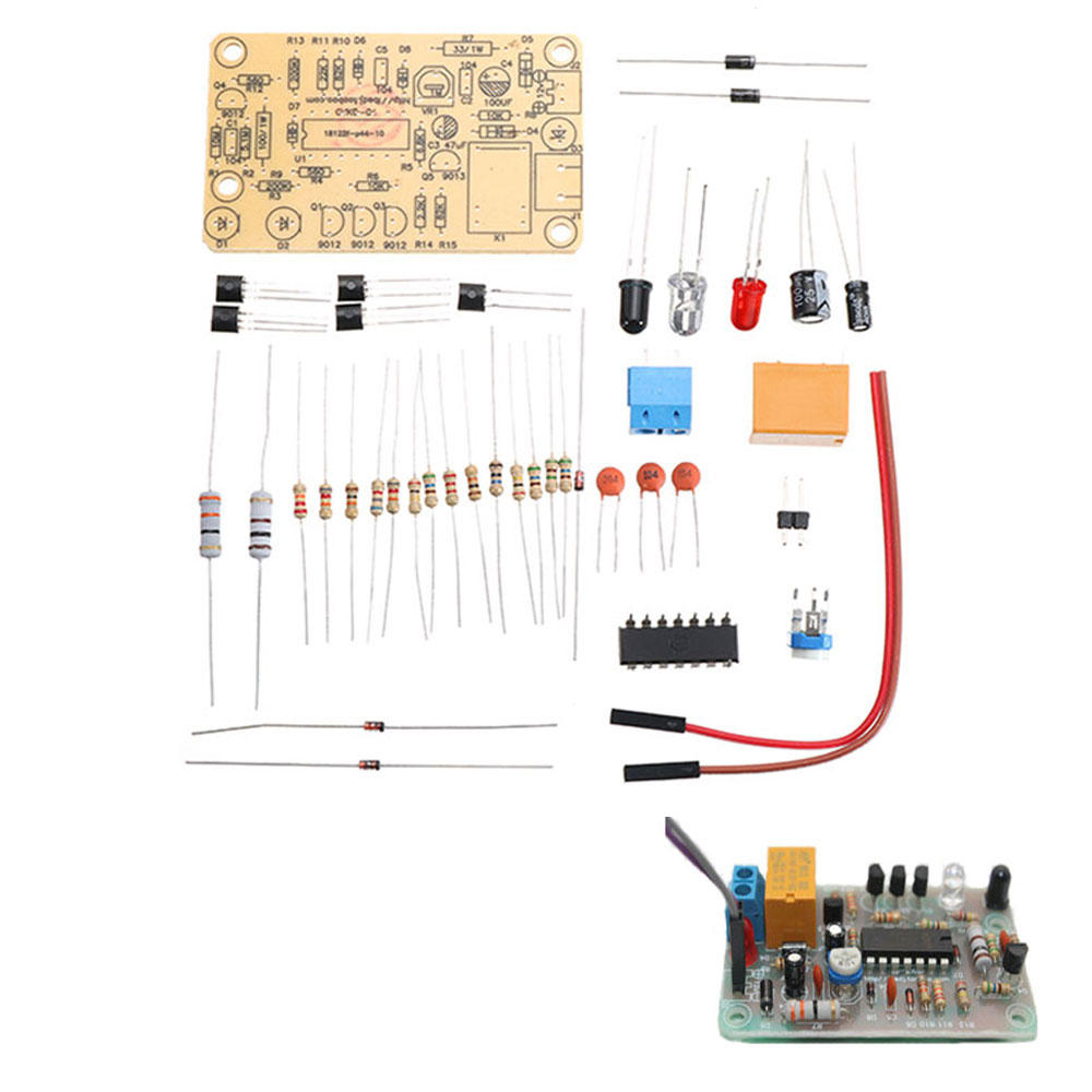
DIY IR Infrared Sensor Switch KitsInfrared Proximity Switch Circuit Board Electronic Training Kits

Eachine1
sku: 1300901
type: Electronic Components & DIY Kits
ACCORDING TO OUR RECORDS THIS PRODUCT IS NOT AVAILABLE NOW
$3.99
Shipping from: China
Description
Parameter Specifications 35 60 1mm length width thickness Operating voltage DC 12V Welding step 1 Solder 14 resistors 2 diodes 3 zener diodes Do not solder in the wrong place pay attention to the positive and negative electrodes when welding diodes and use the negative electrode for the white side It is recommended that the board be mounted tightly 2 Next when welding the HEF4093BP IC do not solder the wrong direction There is a U port on the IC which corresponds to the silk screen on the PCB Solder the transistor after welding the IC Then welding electrolytic capacitors 3 Then solder the adjustable resistor and three led lights to send infrared and black light to receive infrared 4 Welded relays and sockets and 301 2P terminals Circuit description 1 Power circuit input 12V power supply DS can prevent reverse polarity of power supply R7 is current limiting current C2 C4 filter 2 Infrared sensing circuit the oscillator is composed of UIC R10 R1I1 D6 and cs It outputs a pulse signal from pin 10 of U1 After being amplified by Q4 it drives the infrared emitting diode D2 to emit infrared signals to the space If this signal is not blocked by an obstacle the infrared receiver DI cannot receive the signal so the follow up circuit does not work When there is an obstacle in front of the D2 such as the hand shaking in front of the D2 the transmitted infrared signal is reflected back by the obstacle It will be received by DI The received sign
Price history chart & currency exchange rate
Customers also viewed


$12.38
American Style Trendy High-waisted Loose Cargo Pants Bell Bottoms Casual Sweatpants For Women New Arrival Autumn 2024
aliexpress.ru
$49.98
Higher star car 2pcs Front fog lamp decorative cover+2pcs rear fog lamp decorative cover for Toyota Alphard 2015-2019
aliexpress.com
$34.97
Men's Winter Mid-length Windbreaker Hooded Jacket 5 Colors Optional Size M-4XL Plus Velvet Thick Solid Color New Casual Loose
aliexpress.com
$14.99
Christmas Hoodies For Men Women Fleece Sweatshirts Santa Claus Pullover Family Child Couple Clothes
aliexpress.com
$26.15
4x LED Pure White LED Headlight Fog Light Bulbs 6000K Fit For Kia Rio5 2003-2011 FLHRC Road King Classic07-13 Ford Escape01-2004
aliexpress.com
$80.49
Retro leather backpack women men luxury designer genuine leather laptop bag travel bag for male female daypack school backpacks
aliexpress.com
$7.53
Moto Touch Screen Motorbike Racing Riding Gloves Winter Motorcycle Gloves Winter Thermal Fleece Lined Waterproof Heated Guantes
aliexpress.com
$18.12
Two-side Open Pencil Bag Multi Layers Large Capacity Canvas Pen Case Handle Storage Pouch for Stationery School Supplies Gift
aliexpress.com
$19.78
Wall Hole Opener 45/60/65mm Concrete Hole Saw Electric Hollow Core Drill Bit Cement Stone Wall Air Conditioner Mounting w Wrench
aliexpress.com
$15.99
Adjustable Aluminum Bicycle Phone Holder for 3.5" to 6.2" Smartphones GPS MTB Mountain Road Bike Phone Stand Mount Bracket GT
aliexpress.ru

$10.40
Бытовой двухслойный контейнер для пельменей, контейнер для хранения пищевых продуктов, пластиковые контейнеры с крышками, аксессуары
aliexpress.ru
$11.62
New Fashion Female Jogger Pants High Waist Loose Harem Pants Women Slim Pants Hip Hop Casual Trouser
aliexpress.com
")


$252.58
designer herms party garden evening bags for sale new women's 2023 leather cross-body bag with large capacity small design garden
dhgate.com
$23.60
whole link chain fashion women bracelets designer luxury letter chains jewelry 18k gold plated stainless steel bracelet womens2652224, Black
dhgate.com
$35.90
nwt color women yoga shorts back zipper pockeks sports running short exercise workout training 220630, White;black
dhgate.com
$31.91
new t shirt classic foaming letters double layer letters black pink yguang stars trees round neck bat neckline print men womens 2hk1, White;black
dhgate.com
$2.60
Retro Flap Underarm Bag Solid Color Square Bag Trendy Quilted Shoulder Bag Fashion Ladies Lightweight Nylon Handbag
aliexpress.ru
$12.82
Модные серьги, ювелирные изделия в стиле хип-хоп, индивидуальные, в ретро стиле, простые, позолоченные, инкрустированные крестом, в форме кам...
aliexpress.ru
$32.00
Кулеры для процессора ноутбука ThinkPad X280 20KF 20KE Lenovo UMA DELTA FRU PN 01LX665 01LX666 100% Новый оригинальный радиатор для ноутбука
aliexpress.ru

$71.00
Flat Casual Shoes Women Knitted Elastic Shallow Mouth Sneakers Comfortable Breathable Hiking Shoes Outdoor Walking Shoes Larger
aliexpress.com

$28.62
Простой креативный книжный шкаф SG271546 Land, современная простая книжная полка для студентов, для спальни, экономичный витринный шкаф, стеллаж ...
aliexpress.com
$12.50
KALIDI !!Clearance!! Fashion Simple Laptop Bag Notebook Lapto Sleeve Bag For Macbook Air Pro 13 15 Dell Asus HP Acer Laptop Case
aliexpress.com

$0.87
Diamond Painting Full Square/Round Drill 5D Daimond Painting Dog Animal Mosaic Rhinestone Cross Stitch Kids home dccor Gift
aliexpress.com


