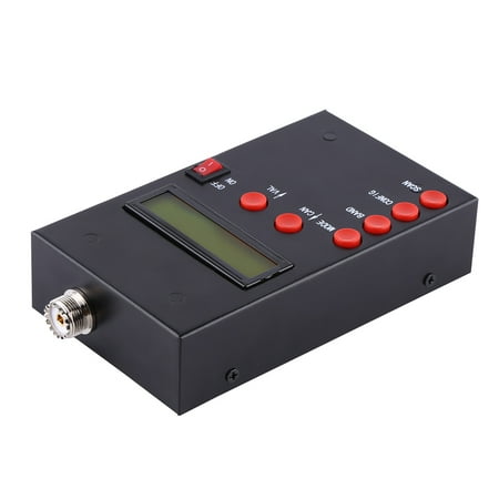
Antenna Analyzer Antenna Meter 12-14V DC 1.0-9.99 Range 1-60MHz For Ham Hobbists For Measurement

sku: 3521013832
ACCORDING TO OUR RECORDS THIS PRODUCT IS NOT AVAILABLE NOW
$100.84
Shipping from: United States
Description
Antenna Analyzer Antenna Meter 12-14V DC 1.0-9.99 Range 1-60MHz for Ham Hobbists for Measurement Specification: Description: This is a SWR analyzer for ham hobbyists. With 5 buttons Mode Band Config Scan Up Down you can selects operation mode band and extended functions. It is powered by DC 12 to 14V 500mA external power with 2.1mm power jack and can be used to measure antenna electrical parameters SWR impedance resistance + reactance capacitance inductance feed-point impedance ground loss etc. Features: SWR usable measurement range of this analyzer is 1.0 to 9.99. step size: user configurable increments of 100Hz 1KHz 10KHz and 100KHz. Powered by DC 12 to 14V 500mA external power with 2.1mm power jackcenter pin positive just connect the power and then work. 5 operation buttons are easy and convenient to operate. You can selects operation mode band and extended functions. Beautiful and simple designed black case would the antenna analyzer from external damage. This would be a great SWR antenna analyzer for ham hobbyist or professionals. Specifications: Frequency Generation & Control: 1 - 60 Mhz Source Impedance: 50 Ohms Stability: +/- 100 ppm Purity: Harmonics down >- TBD dB beyond 60 MHz Step Size: User configurable increments of 100 Hz 1 kHz 10 kHz and 100 kHz SWR Usable Measurement Range: 1.0 to 9.99 Impedance: Approx. 5 to 2000 ohms RF Output: 2.0 Volts pp typ Power Supply: Powered by external 12 to 14V DC 500mA Push Buttons 5: Mode Band Config Scan Up Down Switch: Power On Connectors: RF USB: Mini-B receptacle External Power: 2.1mm Power Jack center pin positive Size: 150 x 90 x 40mm / 5.9 x 3.54 x 1.57 Applications: 1. Measure antenna electrical parameters: SWR impedance resistance + reactance capacitance inductance 2. Measure feed-point impedance 3. Measure ground loss 4. Adjust antenna tuners and determine loss 5. Measure inductors and capacitors 6. Measure coax transmission line SWR length factor approximate Q and loss resonant frequency and impedance 7. Measure and determine settings for tuning stubs: SWR approximate Q resonant frequency bandwidth impedance 8. Determine characteristic impedance of transmission line 9. Coaxial Cable Loss 10. Determine antenna tuner loss 11. Measure balun loss 12. Measure inductor Q 13. Estimate quartz crystal parameters 14. Measure resonance and SWR Operation Button Function: Mode: Selects operation mode impedancedefault complex impedance capacitance and inductance BAND: Select band from any of the available bands 160M to 6M CONFIG: Provides menu for configurations and extended functions PC Link step size setting suspend timeout setting calibration and software upgrade SCAN: Pressing this control initiates a scan of frequencies of the selected BAND. Scan exits to impedance mode showing the 2:1 bandwidth and the resonant point o the antenna CANup: Increase frequency and used to cancel operation for CONFIG menu VALdown: Decrease frequency and used to validate operation for CONFIG menu Package Includes: 1 x AnalyzerPower supply is not included Note: Please note that the new type and
Price history chart & currency exchange rate
Customers also viewed
![Круглые пуговицы из смолы с четырьмя ушками, высококачественные пуговицы для мужских пиджаков, двухсторонние пуговицы для женских шерстяных пальто 1 #[30mm W3365 #four-eye round two-color]](http://img.joomcdn.net/20c630ddbe4e259105034271e26d0c33b8d450d0_original.jpeg "Круглые пуговицы из смолы с четырьмя ушками, высококачественные пуговицы для мужских пиджаков, двухсторонние пуговицы для женских шерстяных пальто 1 #[30mm W3365 #four-eye round two-color]")
$13.80
Круглые пуговицы из смолы с четырьмя ушками, высококачественные пуговицы для мужских пиджаков, двухсторонние пуговицы для женских шерстяных пальто 1 #[30mm W3365 #four-eye round two-color]
joom.ru

$5.08
10 шт. 5/10/20/30/50/100 мл точный наконечник аппликатора капельница для заполнения бутылок клея шейкер игольчатый наконечник бутылка клея для квиллинга ремесло масленка 5ML 10pcs
joom.ru

$26.06
Vintage Scottish Mens Kilt Traditional Skirt Metal Classic Retro Traditional Personality Kilts Check Pattern Basic Kil Skirts
aliexpress.com
$15.85
Men's Vest Jacket Notched Lapel Herringbone Single-Breasted Retro Tooling Fast Shipping Men Waistcoat Tops masculinos homem
aliexpress.com
$49.40
2023 Смарт-часы для мужчин и женщин с Полноразмерным сенсорным экраном спортивные фитнес-часы для мужчин IP67 водонепроницаемые Bluetooth для Android IOS смарт-часы для мужчин
aliexpress.ru
$12.16
Запасные части для бас-гитары, бас-мост, музыкальные инструменты, металлические для большинства гитар
aliexpress.ru
$3.34
Green Mosaic Lattice Phone Cover For iPhone 11 12 13 ProMax XR XS Max 7 8 Plus Soft Four Corner Fall Prevention Protective Shell
aliexpress.com
$1.94
Phone Case for Samsung Galaxy S22 Ultra S21 S20 S10 Plus FE 5G E Note 10 Lite 9 8 One Punch Man Anime Soft Black Silicone Cover
aliexpress.com
$4.38
Disney 3D Donald Lucy Duck Doll Laser Paper Phone Case For Iphone 11 12 13 14 Pro Max Xs Xr 7 8 Plus Clear Soft Rubber Anti-drop
aliexpress.com
$0.99
Giraffe Anime Cute Phone Cases For iphone 14 13 Pro Max case 12 11 Pro Max 8 PLUS 7PLUS 6S XR X XS 6 mini se mobile cell
aliexpress.com
$2.84
Top Brand High Quality Fashion Ma'am Ladies Simple Watches Geneva Faux Leather Wrist Watch Quartz Wrist Watch clock Gift
aliexpress.com
$7.95
beibehang 3d wallpapers building ceiling ceiling photography background modern fresco living room large painting decoration
aliexpress.com
$20.03
Los Angeles 7 Julio Urias Baseball Jersey Dodgers City Blank Stitched Jerseys Men Women Youth Size S--XXXL, Choose number on picture
dhgate.com
$88.14
E5BF Folding Laptop Stand Aluminum Height Adjustable Notebook Cooling Holder Foldable Bracket for All 7-17in Tablets PC
aliexpress.com
$125.54
Motorcycle Saddle bags 70L Large Capacity Side Bag Moto Saddlebags Waterproof Reflective Luggage Suitcase Motorbike Seat Bag
aliexpress.com
$1.68
Volkrays креативные автомобильные стикеры Pet Cat аксессуары Светоотражающие Водонепроницаемые Смешные животные виниловые наклейки черные/сере...
aliexpress.ru

$79.99
Электрический паяльник со светодиодным цифровым дисплеем, Интеллектуальный паяльник в комплекте с адаптером питания 19 в, Электрический па...
aliexpress.com
$5.97
Motorcycloil cap Reservoir Cup caps Engine Oil Filter Cover Cap Accessories For 1290 Super R 2014-2018 2017 2016 2015
aliexpress.com

$54.48
16 Pcs Outdoor Plastic Pots for Plants Flower Planters with Drainage Hole and Tray, 10 Pcs Gray-Black & 6 Pcs Grey
aliexpress.com

$15.01
Women Hoodie Rainbow Sheep Printed Hoodies Women Fleece Long Sleeve O Neck Loose Sweatshirt Girls Pullovers Winter
aliexpress.com
$42.77
DIAPAI Art 5D Diy Diamond Painting "Cartoon snowman" Diamond Pictures Cross Stitch 3D Rhinestone Embroidery Decor A26730
aliexpress.com
$9.98
All Glory To The Hypno Toad Carpet Mat Rug Cushion Soft Hypno Toad Sitcom Animation Science Fiction Comedy
aliexpress.com")


$0.32
1Pcs DIY Dumpling Mould Dumpling Easy Kitchen Tool Dumpling Machine Maker Equipment New Kitchen Tool Home Suppkies Random Color
aliexpress.com
$19.39
Tailored Women Embroidery Thread Chain Small Square Shoulder Bag Wild Little Fairy Bag
joybuy.com
$4.16
Car Retainer Fender Clips Fastener Bumper Cover Retainer Clips Push-Type for Toyota Lexus
joybuy.com
$69.99
LEAGOO M9 3G Phablet 55 inch Android 70 MTK6580A Quad Core 13GHz 2GB RAM 16GB ROM Quad Cameras Fingerprint Scanner
joybuy.com
$5.19
Iridescent Metallic Foil Fringe Curtain Rainbow Tinsel Shimmer Window Door Curtain Wall Backdrop Panel Decoration for Wedding Chri
joybuy.com


$8.95
4GB 8GB 16GB 32GB 64GB 128GB Heart Model Flash Drive Pen Drive Memory Stick USB Flash Disk USB Thumb Drive USB Drive Flash Disk
joybuy.com

$29.99
Half slippers mens summer heels cool lazy people pedal bean shoes mens slippers mens trendy sandals mens wear
joybuy.com


