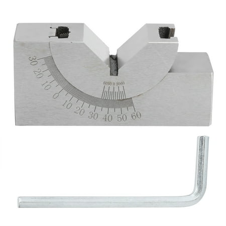
Adjustable Micro Angle Gauge Angle V Block Industrial Tools for Milling Lathe Woodworking Tools
Description
Item Type: Micro Angle Gauge Material: Tool Steel Quenched Nickel Plating Color: As shown in the picture Product Overall Size: Approx.75x36x24mm/2.95x1.42x0.94in Adjuster Size: Approx.22x66x4mm/0.87x2.6x0.16in Weight: Approx.438g/15.4oz Measurement Accuracy: ±0.01mm Application: Use adjustable angle gauges for tool setting scribing or other fixtures to process the workpiece after clamping the workpiece on milling machines planers grinders and drilling machines such as machining bevels drilling oblique holes etc. How to Use: (1). Loosen the screw pull the V-shaped block and rotate it along the guide rail on the base to find the target angle. (2). Using the principle of the cursor to read the division on the main scale is 1° and the scale of the vernier is 10 . When the “0” line on the cursor is aligned with the “0” line on the main scale it means that the measurement surface A is parallel to the reference surface and the reference surface B is perpendicular to the reference surface. ① When the cursor 0 line is to the right of the main scale 0 line the degree is read out with the cursor 0 line and the score is read out with the scale to the right of the cursor 0 line (the reading method is the same as that of the vernier caliper). Degrees (°) and minutes (′) indicate that the A and B measuring surfaces have rotated the angle counterclockwise. ②When the cursor 0 line is to the left of the main scale 0 line the degree is still read out with the cursor 0 line and the score is read out with the scale to the left of the cursor 0 line. Reading degree (°) minute (′) said A and B measure the angle that the surface has turned clockwise. ③After the angle is adjusted to the target value tighten it to tighten the V-shaped block and the base. Main technical indicators: (1) When the measurement surface A is parallel to the base surface and the measurement surface B is perpendicular to the reference surface the misalignment of the vernier “0” line and the main scale “0” line is greater than 3′ and the two 11° lines between the two ends of the vernier and the main scale are not coincident. The coincidence degree is not more than 5′; on the contrary after tightening the screws to align the 0° line of the main scale with the “0” line of the vernier the parallelism between the measurement surface A and the reference surface is not greater than 0.01mm and the perpendicularity between the measurement surface B and the reference surface is also not more than 0.01mm. (2)In the fixed state the indication error of the adjustable angle gauge is not more than ±10′.
Price history chart & currency exchange rate
Customers also viewed


$5.13
Saucier Spoon With Spout Stainless Steel Gravy Ladle Sauce Soup Spoon Kitchen Utensil For Spooning Gravies And Sauces
aliexpress.ru
$33.19
New Genuine Air Conditioning A/C Condenser Tube 97761-2P100 For 2009-2012 Kia Sorento
aliexpress.ru
$41.11
Four Diamonds Stud Earrings 925 Silver Earring for Women Round 4ct Moissanite Stud Earring Engagement Birthday Gift Fine Jewelry
aliexpress.ru
$11.69
Silver and Black Major Arcana Tarot Pattern Short Sleeved Dress women clothing 2025 new arrivals evening dress woman Dress
aliexpress.ru
$7.38
Hot-selling USB Push Button Double-sided Cigarette Lighter Rechargeable Electronic Windproof Men's Gift Cigarette Lighter
aliexpress.ru
$10.33
FalafelGift forFalafel Lovers Apron for home useful pieces for women halloween Kitchen For Men Apron
aliexpress.ru
$10.02
Hello Kitty Women Luxury Brand Bag High Quality Designer Sanrio Cartoon Melody Kuromi Cinnamon Small Crossbody Bags for Girls
aliexpress.ru
$13.46
New Bluetooth 5.0 Lossless MP3 Music Player 2.4 inch Screen HiFi Portable Audio Walkman with FM/eBook/Recorder/MP4 Video Player
aliexpress.ru
$13.24
1pc hot anime cool pink Cat Girl Non-slip Mouse Pad Suitable For Office Computers Laptops E-sports Game Desk Mats XXL Keyboard
aliexpress.ru
$14.52
Girl Children Clothes 3D Cat Print Hoodies Long Sleeve Kids Clothes Casual Kawaii Outdoor Girl Clothing Children Sweatshirt Top
aliexpress.ru
$15.41
1000 шт., пазл с известными пейзажами для детей и взрослых, Лондонская башня, мост, мост, большая игра-головоломка, игрушки, подарок
aliexpress.ru
$14.17
Мужские трусы-боксеры Rudy Pankow с коллажем для фото, Трусы из полиэстера, нижнее белье JJ Homme, трусы с юмором
aliexpress.ru
$17.25
Замок дверной для Liugong lg9055e 55, замок для кабины в сборе, для экскаватора, экскаватора, экскаватора
aliexpress.ru
$71.15
Beaded rhindiamonds hand custom winter plus fleece warm boots Fox fur boots fur one body boots women's large size 35-44
aliexpress.com

$10.59
M18X1.5 CO2 Adapter For Soda Stream Terra Water Maker, For The Connection Of Large CO2 Storage Tanks And Soda Machine
aliexpress.com

$10.92
23Pcs Car LED Interior Lights Lamp Bulbs Kit For BMW X5 E53 2000-2006 White Car Reading Light
aliexpress.com

$100.05
Футболка свободного кроя цвета шампанского с принтом «ковбой» The Laundry Room, черный
cdek.shopping
$29.72
summer girls' suits western style children's sports purple middle-aged short sleeve two-piece girl clothes clothing sets, White
dhgate.com
$67.19
women designer boots ankle boot womens shoes woman martin booties stretch high heel sneaker winter chelsea motorcycle ridingj, Black
dhgate.com
$57.33
men stitch shoes custom sneakers hand paint canvas women fashion black white lows cut breathable walking jogging trainers
dhgate.com

$3,472.28
emslim slimming em slim neo rf arm handle new body contouring stimulator 4 handleiding muscle raise beauty teslashape cool ems machine china
dhgate.com
$11.17
chrleisure mesh high waist fitness leggings women gym workout pu leather femme patchwork joggings dropship 210914, Black
dhgate.com
$85.48
2023 shoulder bag shopping tote bag leather tote bag women designer handbag handbag wallet heart shape women fashion messenger bag
dhgate.com
$90.28
orange grey black cowhide men dress shoes leather style round toe soft-sole fashion business oxfords homme
dhgate.com
$27.62
womens suits plus size two piece set women summer tracksuit lounge wear outfits short sleeve lip print iker shorts sweat suit2300724, White
dhgate.com
$14.12
climbing ropes edc diy copper skeleton king skull ancient warrior man crown retro color knife beads lanyard paracord military charm hangings
dhgate.com
$45.96
spring fashion designers elasitc waist vintage print casual midi pleated skirts womens clothing elegant lady 210601, Black
dhgate.com
$36.72
shoes 270 new mens women running shoes triple shoe max university air olive volt maxes habanero flair 270s sneakers size36-45 wholesale, Black
dhgate.com
$67.12
pink bohemia flower girls dresses for wedding beach ruffles kids formal wear long girl039s pageant gowns2203620, White;blue
dhgate.com
$62.47
makeup sets gold tube lipstick 505 and spray guilty perfumes 75ml charming fragrances exquisite package festival gift
dhgate.com
$57.24
new men's designer hoodie thermal hoodie women's men's women's fashion street fashion pullover loose sports hoodie coupl, Black
dhgate.com
$59.37
michael s kor s m k ggss louisss vuttonss lvss 2023 new arrival 3 pieces set designer bags womens crossbody handbag lady tote coin purse sho
dhgate.com


$48.94
dress shoes large women sandals elegant nigerian pumps shoe for party high quality, Black
dhgate.com
 Boom 11 коричневая 180х190")


