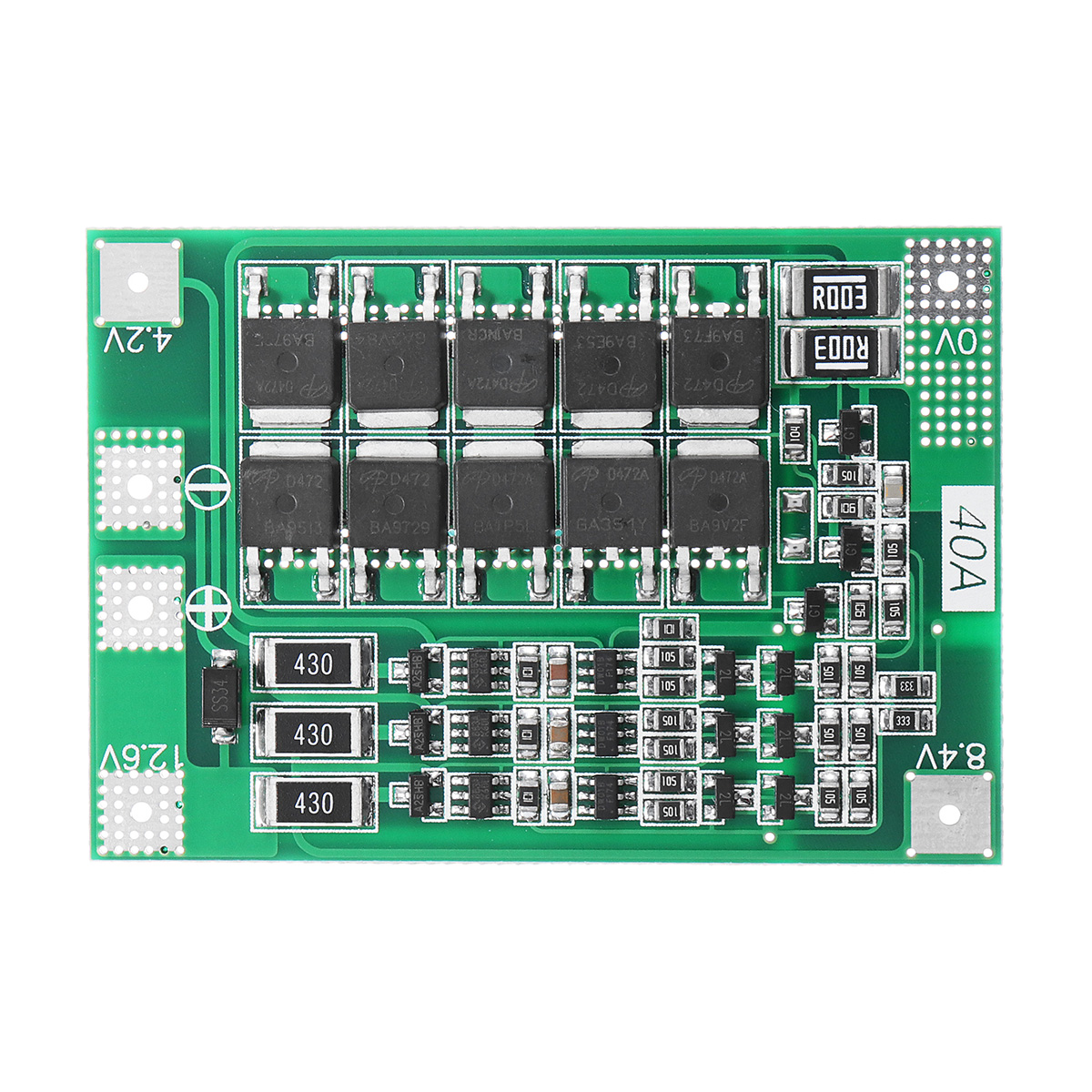
3S 40A Li-ion Lithium Battery Charger Protection Board PCB BMS For Drill Motor 11.1V 12.6V Lipo Cell Module With Balance

Eachine1
sku: 1394450
ACCORDING TO OUR RECORDS THIS PRODUCT IS NOT AVAILABLE NOW
$2.49
Shipping from: China
Description
Description: Suitable for starting current below 80A, power 135W below the drill. (with balance) 3S 12.6V 40A lithium battery protection board (comes with recovery function-AUTO Recovery) Scope: Nominal voltage of 3.6V, 3.7V lithium battery (including 18650,26650, polymer lithium battery) Product Size: 41 * 60 * 3.4mm Product weight: 9.8g Charging voltage: 12.6V - 13.6V Continuous discharge current (upper limit): 40A (if the cooling environment is not good, please reduce the load current use) Continuous charge current (upper limit): 20A Note 1: The successful start of the drill requires three 15C-20C power battery, or six 10C-15C power battery (ordinary 18650 cannot start the drill..). Note 2: Strictly according to map wiring 0V, 4.2V, 8.4V, 12.6V, do not deliberately short circuit. Note 3: When soldering the battery for the first time or while charging, as long as the single battery exceeds 4.2V, the "430" resistor will heat up and discharge (discharge to about 4.19V to stop heating). If the "430" resistor is severely hot, check if the wrong line is connected. For some of the poor basis of electronic customers to explain: Balanced charge is only auxiliary functions, try not to put a good battery and poor battery mixed together. 3 sets of battery capacity / resistance closer to the better. (2 good battery +1 Poor battery use effect = 3 poor battery use effect). Project Min. Typ. Max. Units Notes Consuming current 12 18 24 uA Overcharge protection voltage 4.2 4.25 4.3 V Balanced starting voltage 4.17 4.2 4.23 V Balanced version Equilibrium current 95 100 105 mA Balanced version Balanced heating power 1.17 1.29 1.43 W Balanced version Overcharge recovery voltage 4.1 4.15 4.2 V Over-discharge protection voltage 2.4 2.5 2.6 V Overvoltage protection after over-discharge protection 2.8 3 3.2 V 1C discharge Overvoltage protection after over-discharge protection 3.2 3.5 3.8 V 2C discharge Over-discharge recovery voltage 2.9 3.2 3.3 V Conduction internal resistance 2.5 3 3.5 mQ Overcurrent protection current 70 80 90 A Overcurrent delay time 100 150 200 ms Continuous operating current 0 40 40 A Resistive load Continuous output power 0 504 504 W Resistive load Ambient temperature -40 25 85 C Package includes: 1 x Battery Protection Board Troubleshooting: Fault phenomenon Fault check and cause Approach Unable to charge Measure the voltage of the three groups of batteries. If one of the battery voltages exceeds 4.25V, the protection board will activate overcharge protection. Pair the battery pack well, do not mix the good battery and the bad battery (normal function) Unable to discharge Measure the voltage of the three battery packs. If one of the battery voltages is lower than 2.7V, the protection board will activate the over- discharge protection. Pair the battery pack well, do not mix the good battery and the bad battery (normal function) Charging/discharging failure OV, 4.2V, S.4V, 12.6V miswired Rewiring or replacing a new board (human failure) Overcharge/overdischarge failure OV, 4.2V, 8.4V, 12.6V miswired Rewiring or replacing a new board (human failure) Discharge protection Check that the battery pack has sufficient discharge capability and check that the load's starting current exceeds the overcurrent protection current of the protection board. Replace the battery pack with a higher discharge capacity, or a protective plate with a larger current (super working range) Component soldering There is no connection between one of the components and the PCB pad. Repair welding Component welding There is a short circuit between two or more pins of the component. Remove the component and re-weld Electrostatic breakdown A In the unpowered state, measure the G, D, and S poles of the MOSFET. If the forward and reverse resistances of any two pins are 0Q, it indicates that it has broken down. Remove the replacement MOS tube Electrostatic breakdown B Remove the MOS tube and measure the resistance of the G and D, G and S poles of the MOS tube. If there is a resistance indicating that it has broken down, the resistance should be infinite. Remove the replacement MOS tube
Price history chart & currency exchange rate
Customers also viewed

$66.73
Передняя решетка для Mercedes-Benz W205 C Class 2019-2021 C200 C43 AMG, серебристый гриль + блеск, черный Нижний Бампер, спойлер, сплиттер для губ
aliexpress.ru
$9.31
Zipline пружинный тормоз 165 см из нержавеющей стали Zip Line пружинный тормоз сверхпрочный Zipline тормоз редуктор скорости пружинный тормоз
aliexpress.ru
$12.37
Kids Cartoon Print Hoodies Plus Velvet Baby Boys Girls Long Sleeve Thick Plush Sweatshirts Fleece Lining
aliexpress.com
$57.67
Glossy black Car Rear Roof Spoiler Window Wing Splitter for Volkswagen Scirocco R GTS 2015 2016 2017 2018 MAX Car Styling
aliexpress.com
$65.92
1.37x3m XHT-43164 Shiny Smooth Plain Color Bright Finished Faux Leather Cotton Backing for Making Bag Decoration Hair Bow Craft
aliexpress.com
$1.08
Resin Bunny Ornament Easter Home Miniature Landscape Decoration Cute Animal Rabbit Figurine Dollhouse Miniature Fairy Home Decor
aliexpress.com
$50.96
manufacturers wholesale cotton 32 shares wave wavy bath towel beach towel gift tissue custom set logo gift generation
fordeal.com

$185.74
Colchón Actiflex soft 70x190cm, Grosor: 20 cm, Muelles ensacados, Moderadamente firme, 3 zonas de confort
manomano.es136 cm(ancho)22 cm(fondo) . Color BLANCO-ROBLE")
$178.73
Estanteria alta para oficina,salón acabado blanco/roble 136 cm(alto)136 cm(ancho)22 cm(fondo) . Color BLANCO-ROBLE
manomano.es
 | Rojo")


 Medidas 40X60")
: Blanco Lila")
$1,739.37
Duravit XSquare Vanity unit vertical 81.0 x 47.8 cm, 2 cajones, para lavabo ME de Starck 234683, bol a la derecha, Color (frente/cuerpo): Blanco Lila
manomano.es
$49.53
Farola Solar de LED para Alumbrado Público 40W con Sensor Blanco Frío 6000K | IluminaShop
manomano.es

$162.37
KK7 Pro RC Drone con camara dual 4K 5G Wifi GPS Posicionamiento de flujo optico plegable RC Quadcopter con modo sin cabeza Waypoint Follow Surround
manomano.es

$526.97
Colchon 160X190 POCKET SPRING SUPREME Altura 31 cm Multi-capas efecto nube Muelles ensacados exclusivos en titanio
manomano.es
$96.55
Rugsx - Alfombra de pasillo con refuerzo de goma 80 cm STREIFEN antracita Tonos de gris y plata 80x780 cm
manomano.es


$27.28
anime kimetsu no yaiba nezuko kamado figure led night light for bedroom decor nightlight kids child table 3d lamp mange gift
fordeal.com
$70.03
Póster enmarcado - Vintage Consiglio Flycatchers II Dimensión LxA: 40cm x 30cm, Marco: Roble
manomano.es
$15.17
2 uds., Soporte de exhibicion de pelota de golf, soporte de beisbol acr¨ªlico, soporte para pelota deportiva, soporte para pelota de tenis, soporte
manomano.es
